CAD Generated Schematics & Radiant Design
Tubing Schematic
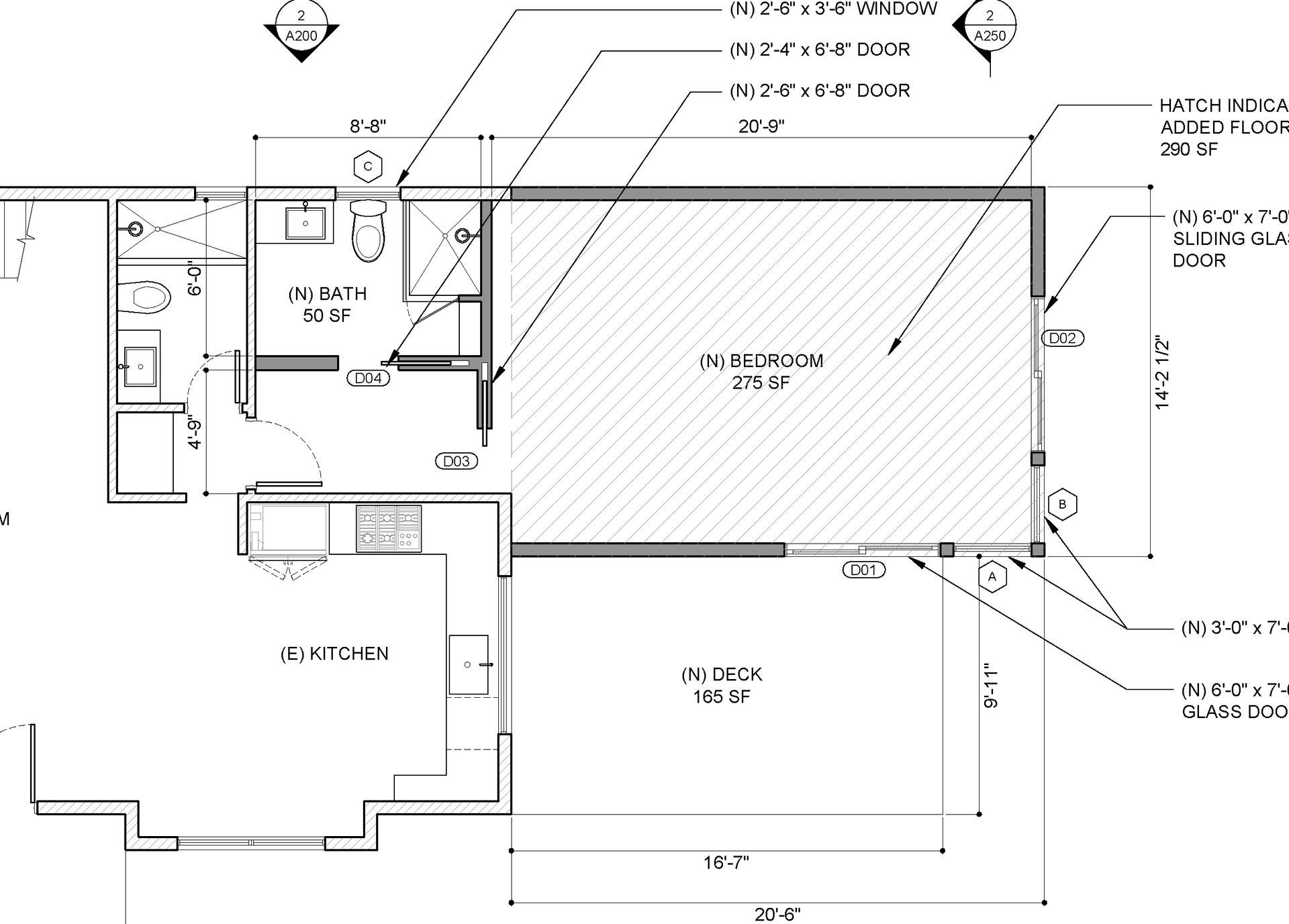
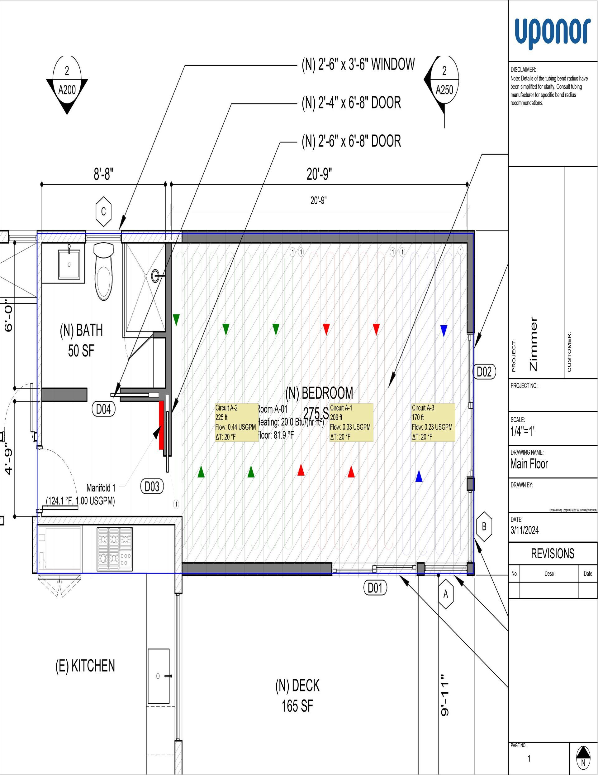
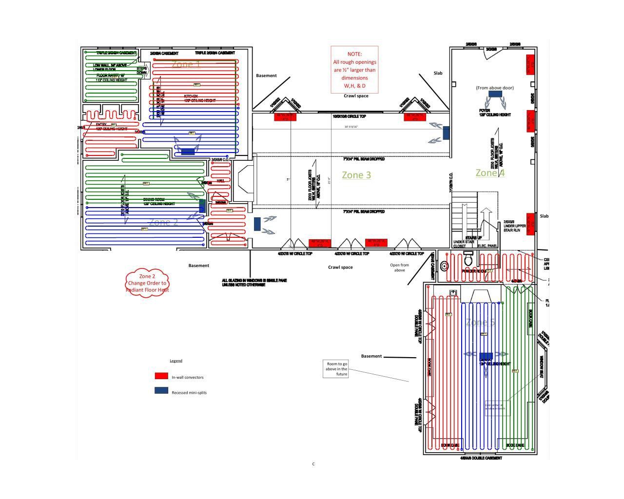
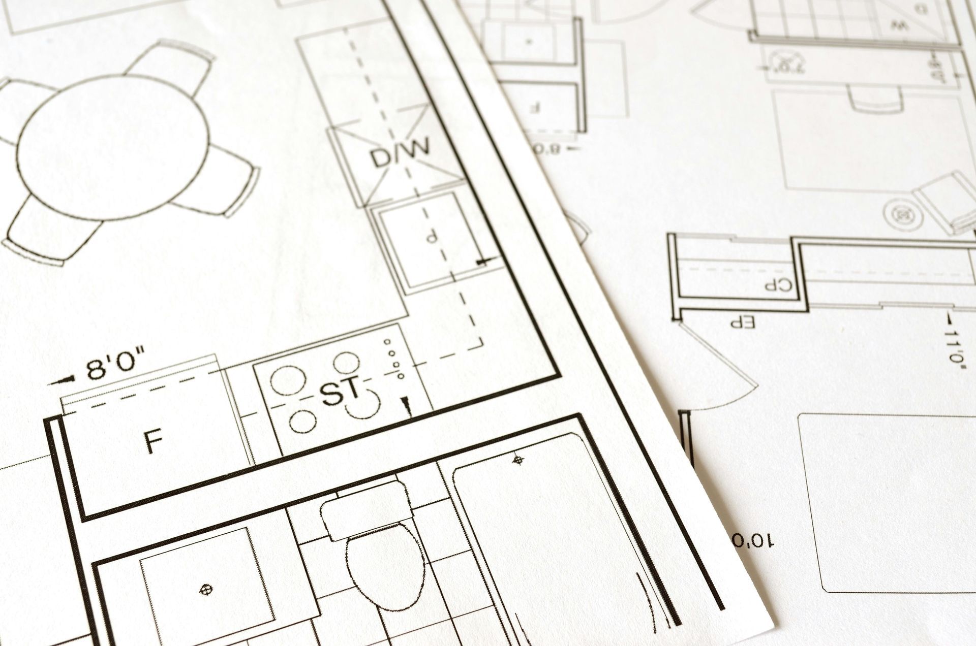
At Advanced Radiant Design, we start with the project’s architect or engineers computer drawings. This way the tubing schematic is accurate to scale on our CAD system and stays consistent with the way the unit will be built. Tubing lengths are determined and adjusted in the design stage and before installation in order to avoid “trial and error” mistakes in the field.
We generate a variety of tubing layouts - each one appropriate to the calculations for a particular room. Here, we optimize the layout to distribute the radiant heat in direct proportion to the heat loss patterns shown in each room. By doing this we ensure even heat distribution and superior comfort
Piping Schematic
Each project’s control piping is also put together from CAD drawings. We find that it is the best way to display all pertinent valves, pumps, and zones clearly labeled along with all schedules. Each and every detail of operation and service is designed in advance and fully integrated before fabrication. The control panel is then built in our shop and is pressure tested for top quality control.
Electrical Schematic
Each control system is pre-wired in the shop from our CAD-generated schematics already fitted with its control functions. Electrical schematics provide details of pump, sensor, and zone schedules. Upon completion, the system controls are pre-programmed, and all control functions are fully tested to ensure flawless performance.
Every radiant project we design is built from our CAD drawings, ensuring that it is installed to precise specifications for the best possible performance. Our CAD drawings also provide a permanent technical description of the system, detailing every aspect of the installation for future reference.